 |
|
|||||||


| Replica Aircraft Topics related to the construction of WWI replica aircraft |
 |
|
|
Thread Tools | Display Modes |
 6 October 2010, 12:58 PM
|
#1 |
|
Forum Ace
Join Date: Dec 2005
Location: Virginia
Posts: 668
 |
More R3600 Prop Math
After watching some of the R3600-powered replicas perform first hand, and seeing the great progress with prop design on other threads, thought a few ideas could be thrown into the ring.
Here are two tables of calculated potential prop specs for use with the R3600 and specific airframes. No warranty, however, just ideas. Since there are few systematic performance data, here are a few ideas on design parameters that might combine form and function. Assumptions: -taking the IAS/TAS figures from originals with specific rotary engines as the starting point, and the Culver pitch calculator at: Culver Propellors -Prop Pitch Calculator, the tables below approximate the R3600 power settings/prop Dia & P for two airframes (Camel and Pup) -the Culver site lists all the relevant assumptions. Basically, they recommend keeping prop tips in the 0.75-0.80 Mach. You punch in a TAS, dia, PRSU and engine RPM, they calculate recommended pitch. No info on prop shape, prop airfoil sections, helical pitch (linear vs increasing). 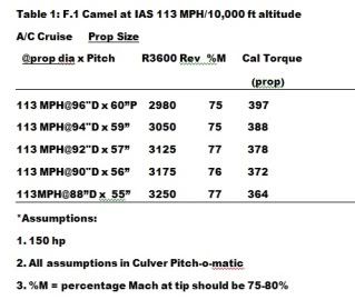  -tables include a few of the props that have been tried here and elsewhere in the attempt to systematically understand the "sweet spot" for R3600 prop dia and pitch. At that point, there are many additional prop 3D shape considerations that might apply at some future time. These are presented to encourage a more systematic approach to R3600 prop design: at $1000-2000 per prop commercial, or a lot of woodworking/prop carving if done by hand, empirical testing would be expensive for key relevant design parameters. Bottom line looks like the R3600/TBI is very promising (see Russ's Camel threads) as a replica powerplant. Sounds like he is getting better thrust than expected. Lots more to do on sorting out which props not only look good, but give the best performance. |

|
| Sponsored Links |
|
|
|
9 October 2010, 05:54 AM
|
#2 |
|
Forum Ace
Join Date: Dec 2005
Location: Virginia
Posts: 668
|
Prop Math Rev 1: Prop dia vs % Mach at tip
Table 3 looks at how % Mach varies with prop diameter. R3600 reported T/O revs 2800-3200, prop diameter, pitch and torque @ 110 MPH/10,000 ft F.1 airframe. Culver recommends %Mach at tip less than 75-80%. No data on prop shape, mx chord, airfoil shapes or tip geometry. Original AD 644 RH (Navy prop for Clerget 130 hp and LeRhone 110 hp; both original engines
@ 1250 rpm) reported as D2590/P2650 or 102x103". 
|
|
|
|
9 October 2010, 08:32 AM
|
#3 |
|
Forum Ace of Aces

Join Date: May 2009
Location: Dayton, Ohio
Posts: 3,338
|
Remember at 2800 rpm you are only at about 75% power, or 112hp
__________________
www.facebook.com/AerodromeLesNoyers |
|
|
|
9 October 2010, 09:34 AM
|
#4 |
|
Forum Ace
Join Date: Dec 2005
Location: Virginia
Posts: 668
|
More Prop Math
This is just thinking out loud about prop design, not actual professional prop engineering.
Not to be taken seriously except to stimulate discussion and experimentation. However, a few educated guesses might save a lot of expense in making various props and having to test empirically for best thrust on a given airframe. Couple of points: 1. In wood props the effective prop disc range is about station 0.3 radius to about 0.95 radius. The inner area has to be thicker than for a metal prop for structural reasons (thin wood airfoil down there would break). The expected thrust from the tip (say, 0.9-1.0 radius) is compromised by turbulence and tip vortices. The latter can be optimized by the tip shape, I believe. 2. On the metal props I have, a thin airfoil is possible down at 0.17 radius. 3. In the prop disc corresponding to stations 0.3 to 0.95, the airfoil section with widest chord might be anywhere. In old props it looks like the widest chord is 0.65 and further out. Placement of the wide chord airfoil is independent of the pitch. 4. In looking at old engine data and applying the Culver algorithm, some interesting questions arise. For example, the fig immediately below is adapted from Fig. 62, Hourwich's 1925 compilation "Air Service Engine Handbook".  I did a double take when it looked like the LeRhoneJ (nominal 110hp) was higher on the chart than the Clerget 9B (nominal 130 hp). However, the normal engine speeds (LeR=1200; Cle9B=1250) check out. Go figure. Two further tables: R3600 run at 2800 RPM (1.5:1 PRSU)  and Clerget run at 1250 RPM (1:1, no PRSU)  Design questions I have are: 1. Where should the widest cord section be on the prop radius to absorb the most engine power for a wood prop? Does optimal placing depend on normal engine speed? (Different for a 1250 rev engine vs a 2800 rev engine)? 2. Maybe the target design criterion for tip velocity should be %Mach down around 50%? 3. For best thrust, should center of pressure of airfoil sections be a straight line, hub to tip, or should it curve toward the leading edge (in side elevation view) like a Garuda prop? This gets into materials flexibility issues (modulus of elasticity of walnut vs mahogany) and glue flexibility (like T88, cascophen and resorcinol vs casein). 4. Period props had straight leading edge (LE) with trailing edge (TE) curved; the converse, curve LE/st TE; and both LE and TE curved. Which gives optimal thrust given engine/airframe combo? 5. The AD 644 has a huge pitch, on the order of Pitch/Dia ratio of 1.00. The Pur Sang Avro has an R3600/84 x 55 prop and seems to fly OK. Pitch/Dia for the Avro is down around 0.65. Last edited by drrivah; 9 October 2010 at 09:44 AM. |
|
|
|
9 October 2010, 09:43 AM
|
#5 |
|
Forum Ace
Join Date: Feb 2005
Location: Norfolk, England
Posts: 1,473
 |
I was wondering about that Pur Sang built Avro. Thats a big aeroplane for the R3600 to haul around. Does anyone have any performance numbers for it. How does it compare with the original?
|
|
|
|
9 October 2010, 11:45 AM
|
#6 |
|
Forum Ace
Join Date: Dec 2005
Location: Virginia
Posts: 668
|
R3600
Boom Powell is best qualified to comment on actual new N504K performance: he flew the Pur Sang Avro 504K/R3600 in September.
It "looked" great from ringside. Appeared the circuits were flown at <1500 ft AGL. The YouTube posts may have vid footage. Flew more like a kite than a rocket. Be very interesting to hear what the original "V-speeds" are for various engine and props. Designed as slow and steady trainer, not high alt/high performance a/c. Jane's says of original with LeRJ /D108" P104" Vmax at ground (MSL?) = 95mph V at 8K @100% power = 87mph 8K @ 75% = 74mph V at 10k@100% = 85mph 10K@ 75% = 71mph Vs ground/full (max wt?) load = 40mph Climb ~625-700 fpm. Total wt = 1829 Rumor is this replica was originally configured with a 100 hp Kinner which was reportedly inadequate. No info on prop tried. Here's another Table: R3600 run at 3200 RPM, constant pitch, looking at how %mach varies with prop dia.  The Culver algorithm does not seem to "like" Pitch/Dia ratio props higher than 0.6-0.7. Also note that the original Pup/LeRhone C (80 hp, 1250 rpm, speed at 10K @ 99 mph) prop spec on original plans (D2600 P2200) gives a Pitch/Dia of ~0.85. The Culver pitch estimator would not have recommended the historically "correct" props if the original engine and airframe data were entered. A lot more "trial and error" will likely be needed before the most efficient prop and power settings for the R3600 are determined for specific airframes, esp. replicas. The relationship between airframe performance, engine and prop spec is complex, but an interesting design challenge. |
|
|
|
9 October 2010, 11:49 AM
|
#7 |
|
Forum Ace
Join Date: Dec 2005
Location: Virginia
Posts: 668
|
Practical Q about thrust measurement on airworthy a/c
When you measure actual thrust on an airworthy airplane, where do you connect the weight scale and the airplane, and with what?
Chain from struts to scale, or fuse harness chained to scale? |
|
|
|
9 October 2010, 03:18 PM
|
#8 | |
|
Forum Ace of Aces
Join Date: May 2009
Location: Dayton, Ohio
Posts: 3,338
|
Quote:
__________________
www.facebook.com/AerodromeLesNoyers |
|
|
|

|
9 October 2010, 05:36 PM
|
#9 | |
|
Forum Ace

Join Date: Oct 2003
Location: Kettering, Ohio
Posts: 2,127
|
Quote:
Prop blade & tips - Airplane wing theory can be applied to propeller theory to help the understanding. As an ideal wing's elliptical lift distribution produces the most efficient lift/drag and so the ideal propeller could be thought of as having the same distribution. So then, the prop tips should be thinned in thickness and tapered in cord. The wings Aspect Ratio (AR) follows too; Higher AR, higher eff. HP needed for flight - This is not a parameter that is derived from trial & error (although flight tests will give more insight on propeller evaluation, but these are small gains in performance). Numerical models (derived many years ago) will model the airplane's drag, lift, weight and thrust. For sustained level flight, the thrust equals the drag (that is min. HP required for level flight) and I think the equations are written in regards to the conservation of energy, so the engines power is one parameter that can be solved for. The additional power of the engine, determines its climb rate. All that info can be roughly modeled in a spreadsheet. The prop is the load on the engine It you have a 150hp capacity engine, but the prop can only load the engine to 75hp, that 75hp is all the engine will produce. Remember, the prop has a rev limit, right? Prop efficiency pointers Remember the larger the prop diameter, the larger the efficiency. The most efficient twist is not really a helix, but there is some twist distribution that prop makers use that is better. Sweep back in a prop blade is extra drag (just like a wing); the leading edge should be as straight as possible. Culvers prop calculator We need to have them show the equations they used, so we can verify their assumptions. Metal vs wooden props Please dont compare the two together, they are very different. Please use only wooden prop examples. Torque/RPM/HP - Torque means NOTHING in the modeling of an aircraft. All the equations have no torque variables, not even a torque variable in a static thrust equation. HP & prop diameter are included, believe it or not! Jan
__________________
Dayton Ohio, The Birthplace of Aviation (Amateur Radio - N8CBX) Last edited by jumpinjan; 9 October 2010 at 05:56 PM. |
|
|
|
|
10 October 2010, 03:57 AM
|
#10 |
|
Forum Ace
Join Date: Dec 2005
Location: Virginia
Posts: 668
|
Prop design & performance challenge
Was hoping an engineer would speak up.
By all means, write a tutorial that would be of practical use in designing and building replica props: I'd buy it. Certainly, the Camel is a well-modeled airframe over the years for flight performance, however the airframe with a high speed engine like the R3600, its particular PRSU and various prop configurations is poorly known territory. On period props, the LE is often curved in plan view, not straight and the TE is straight. As you approach the tip, laminar flow is prematurely separated from the airfoil so the net lift decreases. This can be modeled to minimize the disruption. The point was, how to systematically design an efficient Sop-prop for the engine/airframe that "looks" the part and does the job. Then, how to experimentally verify that the prop design confirms what the theory suggests. I agree it would be useful to see the equations behind the Culver pitch calculator. The algorithm does not seem to generate accurate (ie, historically correct) pitch if the numbers for WW1 era airframe, engine and props are entered. If contemporary airfoil/prop theory and prior modeling algorithms were perfect, a prop design for a Camel/R3600 that duplicated its well-known performance should be possible a priori without experimental testing. Less the rotary engine torque issues, of course. Give it a shot with those equations, Jan: from the grapevine, the R3600 (150 hp nominal) seems to turn 88-90" props. For other prop configurations, T/O revs come in at 2800-3200. What is the best pitch/chord and prop design to approximate classic Camel performance? On a separate issue, I'd like to hear more about engine/prop harmonics, and the flexibility of the various woods used on classic props. Last edited by drrivah; 10 October 2010 at 04:09 AM. |
|
|
|
| Bookmarks |


«
Previous Thread
|
Next Thread
»
 Linear Mode

|
|

 Similar Threads
|
||||
| Thread | Thread Starter | Forum | Replies | Last Post |
| Is it from a prop or not..... | Laserlloyd | Other WWI Aviation | 6 | 21 January 2007 07:56 PM |
| Dr.I prop | baldeagle | Memorabilia | 0 | 19 December 2005 09:32 AM |
| Prop help | rc.gardner | Other WWI Aviation | 2 | 21 July 2005 03:02 AM |
| Do the Math | willycoppens | Models | 19 | 8 April 2003 05:04 AM |
As an Amazon Associate we earn from qualifying purchases.
All times are GMT -7. The time now is 03:08 PM.